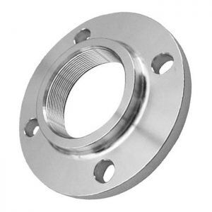
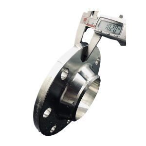
Carbon & Alloy steel Forged Steel Flanges , ASTM/ANSI,JIS,EN,BS Flange
 |
 |
 |
| ASME/ANSI Flanges |
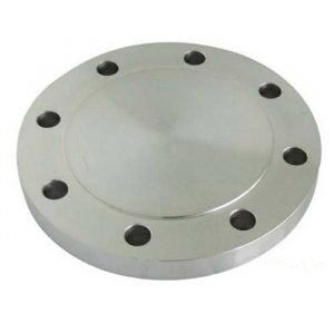
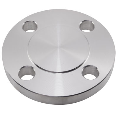
Blind Flange | Carbon Stee Blind Flange |
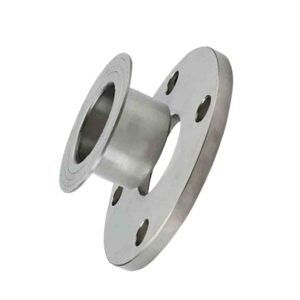 |
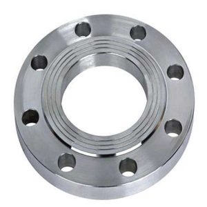 |
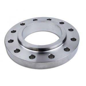 |
| Lap Joint Flange |
Plate Flange | Slip-on Flange |
|
|
|
|
| Socket Weld Flange | Threaded Flange | WELD NECK FLANGE |
Flange size & tolerance
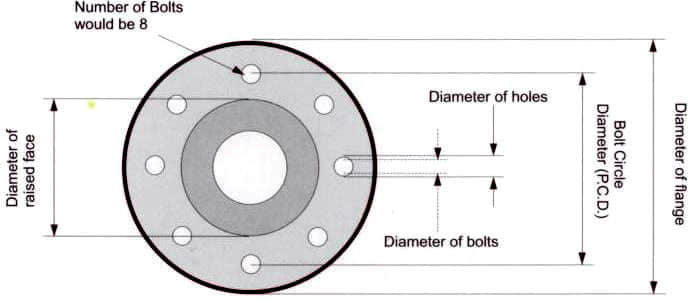
These Flanges are most durable and manufactures to fit in different size of Pipes.
Hengtong group is one of the oldest manufacturers, dealer, distributor, stockist & suppliers of Blind Flanges, Reducing Threaded Flanges, Lap Joint Flanges, Flange Gaskets, Threaded Flanges, Socketweld Flanges, Flanges Bolts, Ring Flange, Spectacle Blind Flanges, Weld Neck Flanges, Orifice Flange, Slip-On-Flanges, High Hub Blinds Flanges, which are manufactured using superior grade of steel like SS Flanges / Stainless Steel Flange, 310 Flanges, 321 Flanges, 202 Flanges, 347 Flanges, 304 Flange, 316 Flanges, 316L Flanges.,
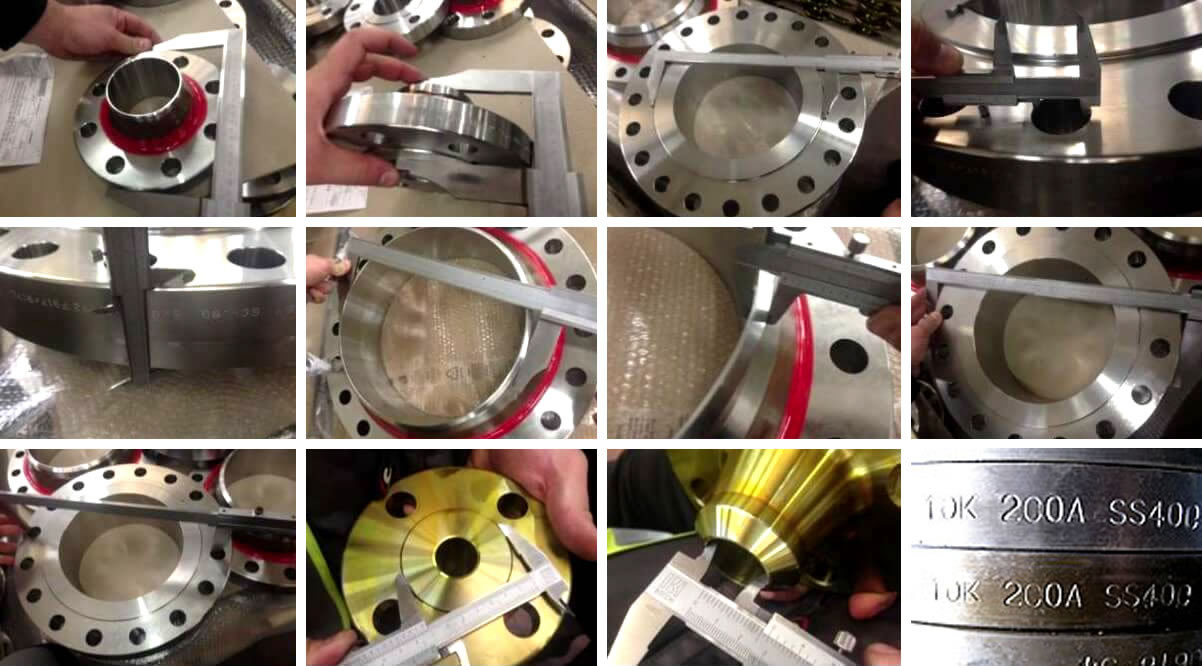
Our company offers a wide range of flanges like PL, SW, BL, WN,SO,LJ, ASME/ANSI B16.5 etc., which is precisely engineered in
Tolerance of Welding Neck Flanges
| Outside Diameter | When O.D. is 24″ or less | ±1.6mm﹡ |
| Inside Diameter | 10″ and smaller | ±0.8mm |
| 12″ thru 18″ | ±1.6mm | |
| 20″ and larger | +3.2mm, -1.6mm | |
| Outside Diameter of hub | 5″ and smaller | +2.4mm, -0.8mm﹡ |
| 6″ and larger | +4.0mm, -0.8mm | |
| Diameter of contact face | 1/16″ rasied face tongue and groove male, female | ±0.8mm |
| 1/4″ rasied face tongue and groove male, female | ±0.4mm | |
| Diameter of hub at base | when hub base is 24″ or smaller | ±1.6mm﹡ |
| Diameter of hub at point of welding | 5″ and smaller | +2.4mm, -0.8mm |
| 6″ and larger | +4.0mm, -0.8mm | |
| Drilling | Bolt circle | ±1.6mm |
| Bolt hole spacing | ±0.8mm | |
| Eccentricity of bolt circle with respect to facing | 2 1/2″ and smaller: 0.8mm, max﹡ | |
| Eccentricity of bolt circle with respect to bore | 3″ and larger: 1.6mm, max﹡ | |
| Thickness | 18″ and smaller | +3.2mm, -0mm |
| 20″ and larger | +4.8mm, -0mm | |
| Length of thru hub | 10″ and smaller | ±1.6mm |
| 12″ and larger | ±3.2mm |
Tolerance of Threaded Flanges, Socket Welding Flanges, Slip-On Flanges
Lap Joint Flanges and Blind Flanges
| Outside Diameter | When O.D. is 24″ or less | ±1.6mm﹡ |
| Inside Diameter | Threaded | Within limits on boring gauge |
| Socket welding, Slip-on and Lap joint, 10″ and smaller | +0.8mm, -0mm | |
| Socket welding, Slip-on and Lap joint, 12″ and larger | +1.6mm, -0mm | |
| Outside Diameter of hub | 5″ and smaller | +2.4mm, -0.8mm﹡ |
| 6″ and larger | +4.0mm, -0.8mm | |
| Diameter of contact face | 1/16″ rasied face tongue and groove male, female | ±0.8mm |
| 1/4″ rasied face tongue and groove male, female | ±0.4mm | |
| Diameter of counterbore | same as for inside diameter | |
| Drilling | Bolt circle | ±1.6mm |
| Bolt hole spacing | ±0.8mm | |
| Eccentricity of bolt circle with respect to facing | 2 1/2″ and smaller: 0.8mm, max﹡ | |
| Eccentricity of bolt circle with respect to bore | 3″ and larger: 1.6mm, max﹡ | |
| Thickness | 18″ and smaller | +3.2mm, -0mm |
| 20″ and larger | +4.8mm, -0mm | |
| Length of thru hub | 10″ and smaller | ±1.6mm |
| 12″ and larger | ±3.2mm | |
Chemical Analysis(%) For Part Standard
The usual materials of flanges include stainless steel, carbon steel, aluminum and plastic.
| Standard | Grade | C | Si | Mn | P | S | V | Nb | Ti | Cr | Mo | Ni | Al | Nb | N | Others |
|---|---|---|---|---|---|---|---|---|---|---|---|---|---|---|---|---|
| max | max | max | max | max | max | max | max | max | max | max | max | max | max | max | ||
| A694 | F42 | 0.28 | – | 1.30 | 0.030 | 0.030 | – | – | – | – | – | – | – | – | – | – |
| F46 | 0.28 | – | 1.40 | 0.030 | 0.030 | – | – | – | – | – | – | – | – | – | – | |
| F52 | 0.28 | – | 1.40 | 0.030 | 0.030 | – | – | – | – | – | – | – | – | – | – | |
| F56 | 0.28 | – | 1.40 | 0.030 | 0.030 | – | – | – | – | – | – | – | – | – | – | |
| F60 | 0.28 | – | 1.40 | 0.030 | 0.030 | – | – | – | – | – | – | – | – | – | – | |
| F65 | 0.28 | – | 1.40 | 0.030 | 0.030 | – | – | – | – | – | – | – | – | – | – | |
| F70 | 0.28 | – | 1.40 | 0.030 | 0.030 | – | – | – | – | – | – | – | – | – | – | |
| A182 | F11 | 0.05-0.15 | 0.50-1.0 | 0.30-0.60 | 0.025 | 0.025 | – | – | – | 1.00-1.50 | 0.44–0.65 | – | – | – | – | – |
| F22 | 0.05-0.15 | 0.50 | 0.30-0.60 | 0.025 | 0.025 | – | – | – | 1.90-2.60 | 0.87–1.13 | – | – | – | – | – | |
| F5 | 0.15 | 0.50 | 0.30-0.60 | 0.025 | 0.025 | – | – | – | 4.00-6.00 | 0.45–0.65 | – | – | – | – | – | |
| F9 | 0.15 | 0.25-1.0 | 0.30-0.60 | 0.025 | 0.025 | – | – | – | 8.00-10.00 | 0.90–1.10 | – | – | – | – | – | |
| F91 | 0.08-0.12 | 0.20-0.50 | 0.30-0.60 | 0.020 | 0.010 | 0.18–0.25 | – | – | 8.00-9.50 | 0.85–1.05 | 0.40 | 0.04 | – | 0.03–0.07 | Cb 0.06–0.10 |
|
| F92 | 0.07-0.13 | 0.5 | 0.30-0.60 | 0.020 | 0.010 | 0.15–0.25 | – | – | 8.50-9.50 | 0.30–0.60 | 0.40 | 0.04 | – | 0.03–0.07 | Cb 0.04–0.09 W 1.5–2.00 B 0.001–0.006 |
Tensile Property For Part Standard
| Standard | Grade | Yield Strengh(Mpa) | Tensile Strengh(Mpa) | Hardness | Elongation(%) | ||
|---|---|---|---|---|---|---|---|
| Min | Max | Min | Max | Max | |||
| A694 | F42 | 290 | – | 415 | – | – | |
| F46 | 320 | – | 435 | – | – | ||
| F52 | 360 | – | 460 | – | – | ||
| F56 | 390 | – | 490 | – | – | ||
| F60 | 415 | – | 520 | – | – | ||
| F65 | 450 | – | 535 | – | – | ||
| F70 | 485 | – | 570 | – | – | ||
| A182 | F11 | 205 | – | 380 | – | – | |
| F22 | 205 | – | 380 | – | – | ||
| F5 | 205 | – | 415 | – | – | ||
| F9 | 205 | – | 415 | – | – | ||
| F91 | 415 | – | 585 | – | – | ||
| F92 | 440 | – | 620 | – | – | ||
Dimensional tolerances for AWWA pipe flanges
Listed below are the Dimensional Tolerances to which flanges are manufactured.
| Ring type Slip-on and Blind flanges | HUB type slip-on | ||||
| O.D. | <=24″ | +/- 0.6″(1.6mm) | O.D. | <=24″ | +/- 0.6″(1.6mm) |
| >24″ | +/- .12″(3.2mm) | >24″ | +/- .12″(3.2mm) | ||
| I.D. | Socket-Welding | 10″ and Samller +.03″(0.8mm),-0″ |
I.D. | 10″ and Samller | +.03″(0.8mm) |
| Slip-on and Lap Joint |
12″ and Larger +.06″(1.6mm),-0″ |
12″-18″ | +/-.06″(1.6mm) | ||
| 20″-42″ | +.12″(3.2mm) +.06″(1.6mm) |
||||
| O.D. of Hub | <=12″ | +.09″(2.4mm), -.06″(1.6mm) |
Diameter of Contact Face |
0.06″ Raised Face | +/-.03″(0.8mm) |
| 14″-42″ | +/-.12″(3.2mm) | ||||
| Diameter of Contact face | 0.06″ Raised Face | +/- .03″(0.8mm) | Diameter of Hub at base | X<=24″ | +/-.06″(1.6mm) |
| X>24″ | +/-.12″(3.2mm) | ||||
| Deameter of Contact face | <=10″ | +.03″(0.8mm), -0″ |
Diameter of Hub at point of Welding | <=5″ | +.09″(2.4mm), -.03″(0.8mm) |
| 12″-42″ | +.06″(1.6mm), -0″ |
>=6″ | +.16″(4.0mm), -.03″(0.8mm) |
||
| Drilling | Bolt Circle | 1/2“-24″ /26″-42” |
Drilling | Bolt Circle | 1/2“-24″ /26″-42” |
| +/-.06″(1.6mm) +/-.06″ |
+/-.06″(1.6mm) +/-.06″ |
||||
| Bolt hole spacing |
+/-.03″(0.8mm) | Bolt hole spacing |
+/-.03″(0.8mm) | ||
| Eccentricity of Bolt circle with respect to bore | .03″ Max. (0.8mm) |
Eccentricity of Bolt circle with respect to bore | .03″ Max. (0.8mm) |
||
| Thickness | 18″& Small | +.12″(3.2mm),-0″ | Thickness | 18″& Small | +.12″(3.2mm),-0″ |
| 20″-42″ | +.19″(1.6mm) | 20″-42″ | +.19″(1.6mm) | ||
| Length Thru Hub | <=10″ | +/-.06″(1.6mm) | Length Thru Hub | <=10″ | +/-.06″(1.6mm) |
| 12″-42″ | +/1.12″(3.2mm) | 12″-42″ | +/1.12″(3.2mm) | ||
These tolerances are a part of ANSI B16.5 and AWWA C207-01 Sec. 4.2 except where noted otherwise. The limits given are maximum. Rigid inspection procedure assures the maintenance of high standards of accuracy in regular day to day production.
ASTM A105 150 Flange dimensions
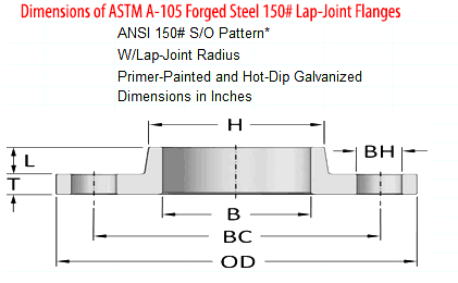
| Nominal Size |
Outside Diameter (OD) |
Bore Diameter (B) |
No. of Bolt Holes |
Bolt Hole Diam. |
Bolt Circle (BC) |
Thickness (T) |
Hub Length (L) |
Hub Diam. (H) |
Lap Radius ( R ) |
Approx. Weight (lbs) |
|---|---|---|---|---|---|---|---|---|---|---|
| 1 | 4.25 | 1.38 | 4 | 0.625 | 3.13 | 0.563 | 0.688 | 1.938 | 0.13 | 2 |
| 1 1/4 | 4.68 | 1.72 | 4 | 0.625 | 3.50 | 0.625 | 0.813 | 2.312 | 0.19 | 3 |
| 1 1/2 | 5.00 | 1.97 | 4 | 0.625 | 3.88 | 0.688 | 0.875 | 2.563 | 0.25 | 3 |
| 2 | 6.00 | 2.46 | 4 | 0.750 | 4.75 | 0.750 | 1.000 | 3.063 | 0.31 | 5 |
| 2 1/2 | 7.00 | 2.97 | 4 | 0.750 | 5.50 | 0.875 | 1.125 | 3.563 | 0.31 | 7 |
| 3 | 7.50 | 3.60 | 4 | 0.750 | 6.00 | 0.938 | 1.188 | 4.250 | 0.38 | 8 |
| 3 1/2 | 8.50 | 4.10 | 8 | 0.750 | 7.00 | 0.938 | 1.250 | 4.812 | 0.38 | 11 |
| 4 | 9.00 | 4.60 | 8 | 0.750 | 7.50 | 0.938 | 1.312 | 5.312 | 0.44 | 13 |
| 5 | 10.00 | 5.69 | 8 | 0.875 | 8.50 | 0.938 | 1.438 | 6.438 | 0.44 | 15 |
| 6 | 11.00 | 6.75 | 8 | 0.875 | 9.50 | 1.000 | 1.562 | 7.562 | 0.50 | 18 |
| 8 | 13.50 | 8.75 | 8 | 0.875 | 11.75 | 1.125 | 1.750 | 9.688 | 0.50 | 30 |
| 10 | 16.00 | 10.92 | 12 | 1.000 | 14.25 | 1.188 | 1.938 | 12.000 | 0.50 | 42 |
| 12 | 19.00 | 12.92 | 12 | 1.000 | 17.00 | 1.250 | 2.188 | 14.375 | 0.50 | 64 |
| 14 | 21.00 | 14.19 | 12 | 1.125 | 18.75 | 1.375 | 2.250 | 15.750 | 0.50 | 90 |
| 16 | 23.50 | 16.19 | 16 | 1.125 | 21.25 | 1.438 | 2.500 | 18.000 | 0.50 | 98 |
| 18 | 25.00 | 18.20 | 16 | 1.250 | 22.75 | 1.562 | 2.688 | 19.875 | 0.50 | 125 |
| 20 | 27.50 | 20.25 | 20 | 1.250 | 25.00 | 1.688 | 2.875 | 22.000 | 0.50 | 160 |
| 24 | 32.00 | 24.25 | 20 | 1.375 | 29.50 | 1.875 | 3.250 | 26.125 | 0.50 | 212 |
| 30** | 38.75 | 30.25 | 28 | 1.375 | 36.00 | 2.125 | 3.500 | 32.750 | 0.50 | 305 |
| 36** | 46.00 | 36.25 | 32 | 1.625 | 42.75 | 2.375 | 3.750 | 39.250 | 0.50 | 440 |
ASTM A105 Blind Flange
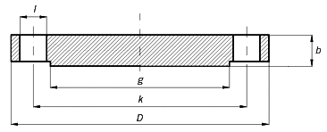
| ø | D | b | g | k | Holes | l | Kg. |
|---|---|---|---|---|---|---|---|
| 1/2″ | 88,9 | 11,1 | 34,9 | 60,3 | 4 | 15,9 | 0,400 |
| 3/4″ | 98,4 | 12,7 | 42,9 | 69,8 | 4 | 15,9 | 0,700 |
| 1″ | 107,9 | 14,3 | 50,8 | 79,4 | 4 | 15,9 | 0,900 |
| 1 1/4″ | 117,5 | 15,9 | 63,5 | 88,9 | 4 | 15,9 | 1,300 |
| 1 1/2″ | 127,0 | 17,5 | 73,0 | 98,4 | 4 | 15,9 | 1,600 |
| 2″ | 152,4 | 19,0 | 92,1 | 120,6 | 4 | 19,0 | 2,600 |
| 2 1/2″ | 177,8 | 22,2 | 104,8 | 139,4 | 4 | 19,0 | 4,100 |
| 3″ | 190,5 | 23,8 | 127,0 | 152,4 | 4 | 19,0 | 5,000 |
| 3 1/2″ | 215,9 | 23,8 | 139,7 | 177,8 | 8 | 19,0 | 6,400 |
| 4″ | 228,6 | 23,8 | 157,2 | 190,5 | 8 | 19,0 | 7,100 |
| 5″ | 254,0 | 23,8 | 185,7 | 215,9 | 8 | 22,2 | 9,000 |
| 6″ | 279,4 | 25,4 | 215,9 | 241,3 | 8 | 22,2 | 11,800 |
| 8″ | 342,9 | 28,6 | 269,9 | 298,4 | 8 | 22,2 | 21,000 |
| 10″ | 406,4 | 30,2 | 323,4 | 361,9 | 12 | 25,4 | 30,000 |
| 12″ | 482,6 | 31,7 | 381,0 | 431,8 | 12 | 25,4 | 45,000 |
| 14″ | 533,4 | 34,9 | 412,7 | 476,2 | 12 | 28,6 | 59,000 |
| 16″ | 596,9 | 36,5 | 469,9 | 539,9 | 16 | 28,6 | 79,000 |
| 18″ | 635,0 | 39,7 | 533,4 | 577,8 | 16 | 31,7 | 97,000 |
| 20″ | 698,5 | 42,9 | 584,2 | 635,0 | 20 | 31,7 | 124,000 |
| 22″ | 749,3 | 46,0 | 641,2 | 692,1 | 20 | 34,9 | 151,000 |
| 24″ | 812,8 | 47,6 | 692,1 | 749,3 | 20 | 34,9 | 188,000 |
ASTM A105 Weld Neck Flange
Materials: ASTM A105
Standards: API, ANSI, BS, JIS, UNI, MSS and SP
Pressure: ANSI class 150 to 2,500
Size: 1/2 to 56 inches (DN15 to DN1,400mm)
Used in: Oil Field, Offshore, Water System, Shipbuilding, Natural Gas, Electric Power, Pipe Projects etc.ASTM A105 Slip on Flange
ASTM A105 Slip on Flange Manufacturer Landee Supplies ASTM A105 Slip on Flanges, ANSI class 150 to 2,500 SO Flange meets API, ANSI, BS, JIS, UNI, MSS, SP Standards.
Type: Slip-on Flange
Materials: ASTM A105
Standards: API, ANSI, BS, JIS, UNI, MSS and SP
Pressure: ANSI class 150 to 2,500
Size range: 1/2 to 56 inches (DN15 to DN1,400mm)
Used in: Oil Field, Offshore, Water System, Shipbuilding, Natural Gas, Electric Power, Pipe Projects etc.
Industry Specification for Pipe Flange
Before we dive in to the different types of flange, it is important to understand the industry specification it conforms to. So what is ANSI Flange, AWWA Flange and ASME Flange? What is the difference between ANSI Flange and ASME Flange? What is the difference between Series A and Series B Flange. We will answer all these questions.
There are four types of industry standards covering different flange types;
- ANSI Flange, also called ASME B16.5 Flange
- ASME Flange, also called ASME B16.47 Flange (Series A and Series B)
- Industry Standard Flange (ASME B16.1 Flange)
- AWWA Flange
| Material | : | 1. Stainless Steel ASTM/ASME A/SA182 F304, F304L, F316, F316L, ASTM/ASME A/SA351 CF8, CF3, CF8M, CF3M, DIN1.4301, DIN1.4306, DIN1.4401, DIN1.4404, DIN1.4308, DIN1.4408, DIN1.4306, DIN1.4409 2. Carbon Steel ASTM/ASME A/SA105 A/SA105N & A/SA216-WCB, DIN1.0402, DIN1.0460, DIN1.0619 |
| Dimension | : | ANSI/ASME B16.5, ANSI/ASME B16.47 Series A (MSS SP-44), ANSI/ASME B16.47 Series B (API 605), ANSI/ASME B16.36, ANSI/ASME B16.48 (API 590) |
| Size | : | 1/2″ (DN15) ~ 60″ (DN1500) |
| Pressure | : | Class 150, Class 300, Class 400, Class 600, Class 900, Class1500, Class 2500 |
| Type | : | Weld Neck, Threaded, Slip-On, Socket Weld, Lap Joint, Blind, Orifice Flange, Orifice Plate and Restriction Orifice Plate, Spectacle Blind, Spacer, Blanks |
| Face Type | : | Flat Face (FF), Raise Face (RF), Ring Joint (RJT) |
| Coating | : | Anti-rust Paint, Oil Black Paint, Yellow Transparent, Zinc Plated, Cold and Hot Dip Galvanized |
ASME B16.5 pipe flange and flanged fittings cover sizes from 1/2″ nominal to 24″ nominal. The standard covers pressure, temperature, material, tolerance, dimension, testing and marking of flange. The pressure classed included in ASME B16.5 are 150#, 300#, 600#, 900# and 1500# for sizes up to 10″ nominal and 2500# for sizes 12″ through 24″.
ASME B16.5 standard is limited to flanges made from cast or forged material.
ASME B16.47 Series A and Series B Flange Specification
ASME B16.47 covers large diameter steel flanges from 26″ nominal to 60″ nominal pipe sizes. There are two types of B16.47 flanes, Series A and Series B. Both have slightly different dimensions such as thickness, bolt circle diameter and number of bolt holes. Pressure class covered by B16.47 is Class 75, 150, 300, 400, 600 and 900#. Standard covers flanges made of cast, forged or plate material (for blind flange only).
What is the difference between ASME B16.47 Series A and Series B (API605) flanges?
ASME B16.5 standard covers Steel Pipe Flanges and Flanged Fittings from NPS 1/2 through NPS 24 Metric/Inch in pressure class 150 to class 2500. It covers pressure-temperature ratings, materials, dimensions, tolerances, marking, testing, and methods of designating openings for pipe flanges and flanged fittings. Two very important flanges such as weld neck flange and blind flanges are very commonly used in piping systems. The term “B16.5” or “B16 5″ is used interchangeability and refers to same standard. However, the standard ASME B16 5 (ANSI B16 5) only covers size up to 24 inches. For bigger sizes, ASME B16.47 standard covers pressure-temperature ratings, materials, dimensions, tolerances, marking, and testing for pipe flanges in sizes NPS 26 through NPS 60 and in ratings Classes 75, 150, 300, 400, 600, and 900.
However, the standard ASME B16.47 is further divided into ASME B16.47 series A and ASME B16.47 series B flange for Blind flange and Weldneck flange. Series B flange was also formerly known as API 605 flange. Term B16.47 or B 16 47 or ANSI B 16 47 are all used interchangeabily and refers to the same standard.
The ASME B16.47 standard incorporate MSS SP-44: Steel Pipe Flanges and API 605: Large Diameter Flanges for Carbon Steel. Hence MSS SP44 flanges are equivalent to Series A flange where as API 605 flanges are equivalent to Series B flange. Materials covered in this standard are as that in ASME / ANSI B16.5 except for nickel alloys. They also share the same pressure temperature rating as B16.5 flanges.
So what is the difference between ASME B16.47 Series A and Series B (API605) flanges?
ASME B16 47 Series A flanges are much thicker, heavier and stronger than Series B flanges for the same pressure ans size. Series A flange can withstand more external loading than Series B flange. ASME B16.47 Series B flanges need smaller fasteners, in larger quantity, than Series A flanges. They also have a smaller bolt circle diameter than that of Series A flanges. The smaller bolt circle diameter results in less flange movement after installation. Both Series A and Series B standards define weld neck flanges and blind flanges in raised face type (RF) but only Series A defines ring type joint (RTJ) flanges from Class 300 through Class 900 within this standard. Price wise, ASME B16.47 Series A flanges are more expensive than ASME B16 47 Series B flanges.
Most piping users or designers may choose Series A flanges for the new pipeline or equipment. But if you are doing some refurbishment, replacement job or non-critical piping design, Series B flanges are more popular.
See documents below for comparison of flange sizes in two main standards (B16.5 and B16.47)
Flange Dimensions as per ASME B 16 5 standard for 150# Welding Neck Flange, Blind Flange, Slipon, Socketweld & Lapjoint flange is here
Flange Dimensions as per ASME B16 47 series A standard for 150# weldneck and blind flange is here
Flange Dimensions as per ASME B 16.47 series B standard for 150# weld neck and blind flange is here
Conclusions: Standard weld neck, slip on, blind etc. flanges are covered by standard B16.5 for sizes up to 24″ nominal pipe. Sizes 26” and bigger are covered by B16.47 series A or series B for weldneck and blind flanges. Series A flange is heavier, thicker and cost more whereas series B flange has more bolt holes and is lighter cheaper than series A. API605 flange and series B flanges are same thing.
Industry Standard Flange (ASME B16.1 Flange)
No national standard or governing body controls the Industry Standard Flange. The dimension and material of Industry Standard Flange has been adopted after years of “common” industry practice. It is important to note that size and material of industry standard flange are covered by standard ASME B16.1 whic his a standard for Class 25, 125 and 250 Cast Iron Pipe Flange and Flanged Fittings. Pressure rating of industry flange matches the AWWA table 4 class E standard. In sizes smaller than 24″, Industry Standard Flange also matches B16.5 flanges.
AWWA Flange
This standard covers slip-on and blind flanges for waterworks service in sizes 4″ through 144″ nominal (100mm through 3600 mm).
Difference between ANSI and AWWA flange
We have already covered that ANSI flange means ASME B16.5 flange. ANSI and AWWA standard for flanges differ in several ways. The AWWA standard is intended for potable water use. Where as ANSI/ASME standard is aimed at industrial application. AWWA flange rating are applicable only at atmospheric temperature whereas ANSI rating covers from -20°F to 1500°F.
The two standards also differ in the scope of application. ANSI standard includes information for welding auxiliar connections while AWWA does not cover the installations. The AWWA standard only covers hub-type, ring, blind and threaded flange whereas ANSI standard has more types such as weld neck, lap joint, socket weld flange etc.
Standards covering AWWA and ANSI flanges are;
- ANSI/AWWA C115/A21.15-99: “American National Standard for Flanged Ductile-Iron Pipe with Ductile-Iron or Gray-Iron Threaded Flanges”
- ANSI/AWWA C207-94: “AWWA Standard for Steel Pipe Flanges for Waterworks Service-Sizes 4 In. Through 144 In.”
- ANSI / ASME B16.5-1981: “Pipe Flanges and Flanged Fittings”.
| Material | : | 1. Stainless Steel ASTM/ASME A/SA182 F304, F304L, F316, F316L, ASTM/ASME A/SA351 CF8, CF3, CF8M, CF3M, DIN1.4301, DIN1.4306, DIN1.4401, DIN1.4404, DIN1.4308, DIN1.4408, DIN1.4306, DIN1.4409 2. Carbon Steel ASTM/ASME A/SA105 A/SA105N & A/SA216-WCB, DIN1.0402, DIN1.0460, DIN1.0619 |
| Dimension | : | BS10 Table D, E, F, H, J, K, R, S, T, BS4504 Code 101, 105, 111, 112, 113, BS1042 |
| Size | : | DN10 ~ DN4000 |
| Pressure | : | PN2.5, PN6, PN10, PN16, PN25, PN40, PN64, PN100 |
| Type | : | Weld Neck, Threaded Boss, Slip-On Boss, Socket Weld, Plate Blind, Plate, Orifice Plate |
| Face Type | : | Flat Face (FF), Raise Face (RF), Ring Joint (RJT) |
| Coating | : | Anti-rust Paint, Oil Black Paint, Yellow Transparent, Zinc Plated, Cold and Hot Dip Galvanize |
| Material | : | 1. Stainless Steel ASTM/ASME A/SA182 F304, F304L, F316, F316L, ASTM/ASME A/SA351 CF8, CF3, CF8M, CF3M, DIN1.4301, DIN1.4306, DIN1.4401, DIN1.4404, DIN1.4308, DIN1.4408, DIN1.4306, DIN1.4409 2. Carbon Steel ASTM/ASME A/SA105 A/SA105N & A216-WCB, DIN1.0402, DIN1.0460, DIN1.0619 |
| Dimension | : | DIN2527, DIN2573, DIN2576, DIN2502, DIN2503, DIN2543, DIN2544, DIN2545, DIN2630, DIN2631, DIN2632, DIN2633, DIN2634, DIN2635, DIN2636, DIN2637, DIN2638, DIN2628, DIN2629, DIN2627, DIN2641, DIN2642, DIN2652, DIN2653, DIN2655, DIN2656, DIN2673, DIN2674, DIN2675, DIN2676, DIN2558, DIN2561, DIN2565, DIN2566, DIN2567, DIN2568, DIN2569, DIN28115, DIN86029, DIN86030 |
| Size | : | DN10 ~ DN4000 |
| Pressure | : | PN1, PN2.5, PN6, PN10, PN16, PN25, PN40, PN64, PN100, PN160, PN250, PN320, PN400 |
| Type | : | Blind, Slip-On, Weld Neck, Lapped (Lapped Joint), Plain Collar, Loose Flange and Ring for Weld (Slip-On Flange and Plain Collar), Loose Flange and Ring with Neck for Welding, Oval Plain Threaded, Oval with Neck Threaded, Threaded with Neck, Long Neck Welding, Hubbed Slip On for Welding |
| Face Type | : | Flat Face (FF), Raise Face (RF), Ring Joint (RJT) |
| Coating | : | Anti-rust Paint, Oil Black Paint, Yellow Transparent, Zinc Plated, Cold and Hot Dip Galvanize |
| Material | : | 1. Stainless Steel ASTM/ASME A/SA182 F304, F304L, F316, F316L, ASTM/ASME A/SA351 CF8, CF3, CF8M, CF3M, DIN1.4301, DIN1.4306, DIN1.4401, DIN1.4404, DIN1.4308, DIN1.4408, DIN1.4306, DIN1.4409 2. Carbon Steel ASTM/ASME A/SA105 A/SA105N & A/SA216-WCB, DIN1.0402, DIN1.0460, DIN1.0619 |
| Dimension | : | EN 1092-1 |
| Size | : | DN10 ~ DN4000 |
| Pressure | : | PN2.5, PN6, PN10, PN16, PN25, PN40, PN63, PN100, PN160, PN250, PN320, PN400 |
| Type No. | : | Type 01 Plate Flange (slip on) for Welding, Type 02 Loose Plate Flanges with Weld On Plate Collar or for lapped pipe end, Type 04 Loose Plate Flanges with Weld Neck Collar, Type 05 Blind Flange, Type 11 Weld Neck Flange, Type 12 Hubbed Slip On Flanges for Welding, Type 13 Hubbed Threaded Flanges, Type 21 Integral Flange, Type 32 Weld on Plate Collar, Type 33 Lapped Pipe End, Type 34 Weld neck Collar, Type 35 Welding Neck, Type 36 Pressed collar with long neck, Type 37 Pressed Collar |
| Face Type | : | A – Flat Face (FF), B – Raised Face (RF), C – Tongue, D – Groove, E – Spigot, F – Recess, G – O-ring spigot, H – O’ring groove |
| Coating | : | Anti-rust Paint, Oil Black Paint, Yellow Transparent, Zinc Plated, Cold and Hot Dip Galvanize |
| Material | : | 1. Stainless Steel ASTM/ASME A/SA182 F304, F304L, F316, F316L, ASTM/ASME A/SA351 CF8, CF3, CF8M, CF3M, DIN1.4301, DIN1.4306, DIN1.4401, DIN1.4404, DIN1.4308, DIN1.4408, DIN1.4306, DIN1.4409 2. Carbon Steel ASTM/ASME A/SA105 A/SA105N & A/SA216-WCB, DIN1.0402, DIN1.0460, DIN1.0619 |
| Dimension | : | JIS B2220 |
| Size | : | 3/8″ (10A) ~ 60″ (1500A) |
| Pressure | : | 2K, 5K, 10K, 16K, 20K, 30K, 40K and 63K |
| Type | : | Blind, Slip-On, Plate, Weld Neck |
| Face Type | : | Flat Face (FF), Raise Face (RF) |
| Coating | : | Anti-rust Paint, Oil Black Paint, Yellow Transparent, Zinc Plated, Cold and Hot Dip Galvanize |


